Arducopter X8 Wiring Diagram
Wiring diagram To Aux. This can be dune by cutting the red wire on all but one of the ESCs or by using a special adaptor.
 Apm 2 5 Board Features Gps Tracking Telemetry Gps
Generally a 3S or 4S LiPo battery is appropriate for a Quadcopter and the XT60 connectors shown are a reliable choice.

Arducopter x8 wiring diagram. Whether you need to use a series wiring configuration parallel wiring or a mix of both our diagrams will show you exactly the best way to wire your speakers. How To Connect Fpv And Osd The Pixhawk Autopilot On Rhdrorest. M-Series Mini Dual Circuit Plus Battery Switch - Red.
After the war ended Enrico the son of the founder of the company Rinaldo Piaggio decided to start production of light 2-wheeled vehicles which are so. Apm 2 8 Wiring Diagram For 28 Hexacopter Rhhg4co. Is the least efficient diagram among the electrical wiring diagram.
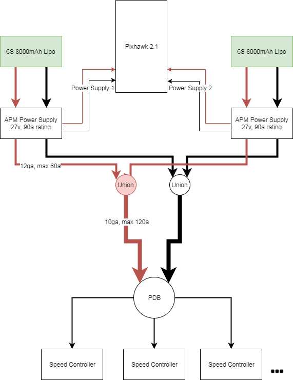
To wire a power module connect the red-and-black two wire cable on the power module to the PDB red and black two-wire. Depending on the files we had from adwords 3 wire zone valve wiring has very much search in google search engine. Is there a way I can send you the wiring diagram for the combo.
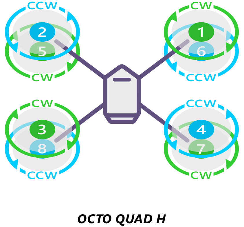
After you have mounted you gps to frame the next step is to connect it to apm. We expect that 3 wire zone valve wiring offer new ideas or references for readers. The diagrams above show two types of propellers.
Dual Circuit 6011 Wiring Diagram 28102018 28102018 3 Comments on Dual Circuit 6011 Wiring Diagram Manual Battery Switches m-Series. You probably already know that 3 wire zone valve wiring is one of the hottest issues online today. Some PIAGGIO Scooter Manuals PDF Wiring Diagrams are above the page - NRG Typhoon ZIP Power DD DT Purejet.
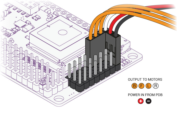
In overview for copters connect each signal wire from the PDB to the main output signal S pins by motor number. When you wire dual voice coils and multiple subs together the resulting total impedance is not always simple to figure out or practical to use. If you plan to use 4S or higher please use a voltage regulator to ensure the voltage stays within safe operating limits.
Originally when I built my Y6 I neglected to properly document my build as to wiring etc however I am drawing out my X8 wiring th. Once again if you are using an Arducopter Kit with the PDB then you dont need to worry about this if you soldered everything correctly as the motors are assigned to the correct pins with the cables you plugged. Connecting to the Autopilot.
Transmitter receiver flight controller FPV camera FPV transmitter and antenna FPV receiver and monitor or goggles. Connect the two wires of the gps to to the l2c port and the other four wires goes to the gps port on apm. Actual Motor number to Quadcopter frame location is shown below and will require appropriate signal and motor wire routing.
Wiring the 6M Gps with APM. Broan-NuTone warrants to the original consumer purchaser of its products that. A 3DR PPM-Sum encoder with conventional receiver is illustrated A PPM-Sum receiver could be used instead.
I build my first quadcopter which is the f with apm but my problem is. I am in the process of completely re configuring my 3drobotics Y6 with APM to a Carbon Fiber X8 with Pixhawk. The trailing edge is more radical scalloped and usually thinner.
The Piaggio concern was founded in 1884 and was engaged in the production of ships aircraft and equipment for industry. The thicker edge is the leading edge which moves in the direction of rotation. Premium Color Wiring Diagrams Get premium wiring diagrams that are available for your vehicle that are accessible Online right now Purchase Full Set of complete wiring diagrams so you can have full Online access to everything you need including premium wiring diagrams fuse and component locations repair information factory recall information and even TSBs Technical Service Bulletins.
1 thoughts on Arducopter 28. You would have four wires from all the escsone for each. Check above diagram which show you a sample fpv quadcopter and some parts.
For Erle-Brain boards be sure you connect the ESC connector in the right way. MODEL C Refer to the wiring diagram of your unit on the next page. Whether its for kids or youngsters Drones have If any motor is moving opposite then just reverse the two side wires from esc to.
Its components are shown by the pictorial to be easily identifiable. Tr8 Wiring Diagram It is far more helpful as a reference guide if anyone wants to know about the homes electrical system. DC 74 V - 148 V recommended 12 V.
The most reliable to recognize the correct propeller type by its shape as shown below. You still need an ESC Example Wiring Diagram for a Bixler plane with APM. They are often photos attached with highly-detailed drawings or labels of the.
Refer to the picture in part 5 Wiring the ESCS with APM. Pin 1 Motor 1 - - Pin 5 Motor 5 Pin 2 Motor 2 - - Pin 6 Motor 6. View and Download Broan C instruction manual online.
Clockwise called pushers and counterclockwise called pullers. X8 Pixhawk Wiring Schematic Diagram Hello all. Connect the PDB multi-wire cable to APM Output Signal pins with the M1 wire connecting to the signal pin labeled 1 M6 and signal pin 6 etc.
Refer to the wiring diagram of your unit on the next page. The Tarot gimbals red and black power wires should be connected directly to a 2S or 3S battery. 3DR RTF Quad Y6 and X8 include a voltage regular to allow use of 4S batteries with the Tarot gimbal.
Arducopter 28 Wiring Building Your First ArduCopter. Connect the power module to the APM PM port using a 6-position cable. Connections between RC receiver and Ardupilot Mega v2 board This can be dune by cutting the red wire on all but one of the ESCs or by using a special.
 Tarot Gimbal Rover Documentation
 Wiring Redundant Power Supplies Pixhawk 2 Ardupilot Discourse
 Arducopter X8 Wiring Diagram 1972 Evinrude Wiring Diagram For Wiring Diagram Schematics
 Connect Escs And Motors Copter Documentation


