Old Carrier Wiring Diagrams For Vav Boxes
VAV Box Location - Since VAV boxes must be located in the branch ductwork they are often placed above the ceiling. Optional accessories may be packed within the unit or in the same shipping carton.
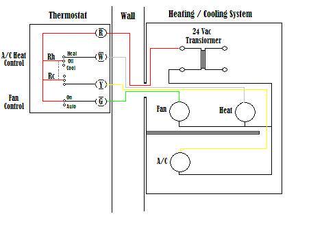
In Article Electrical Wiring Diagrams for Air Conditioning Systems Part Two I explained the electrical wiring diagrams for some Typical Air conditioning equipments.

Old carrier wiring diagrams for vav boxes. VAV-SVN01E-EN 3 Service Model. Assortment of carrier ac wiring diagram. There are different types of Variable Air Volume boxes but how a Variable.
When applicable electrical control and piping diagrams are shown on labels attached to the exterior of the single. Assortment of carrier heat pump wiring diagram. 2 VAV ControllerVariable Air Volume VAV Controller Wiring Details Page 25 Power Source and Loads 26 Grounding and Isolation 27 IO and Communication Terminals 29 Power Zone Bus and N2 Connections 36 Analog Inputs 36.
All field wiring is to be in accordance with the National Electrical Code ANSINFPA No. 11-808-432-01 6212011 VAV Zone Controllers i. How VAV Boxes Work.
Installation Operator Maintenance VariTrane Single-Duct and Fan-Powered Units June 2006 VAV-SVN01E-EN All VariTrane VAV Models with pneumatic electronic DDC controls and diffusers. Today I will explain Electrical Wiring. A wiring diagram is a simplified traditional pictorial depiction of an electrical circuit.
It shows the elements of the circuit as simplified shapes and the power as well as. DDC-IOM August 1997 1997 Environmental Technologies Inc. All field wiring must comply with the local codes and with the National Electrical Code ANSINFPA 70-2002.
Models MQTHI5 MQFCI6 MQFVI5 Terminal. VAV piping packages as well as HL HP VF and VL fan coil unit packages are factory assembled and shipped loose for field installation and wiring. Each complete terminal with electric.
VAV Zone Controllers Installation and Start-up Guide CARRIER CORPORATION 2011 A member of the United Technologies Corporation family Stock symbol UTX Catalog No. Presented by Nick Searle this webinar focused on basic concepts and system benefits of VAV diffusers being used in HVAC systems. All VH fan coil unit packages.
Variable-Air-Volume VAV Box Controller VAV-SVX07-EN Tracer UC400 Programmable BACnet Controller for VAV Units VAV-SVP01-EN VAV VV550 LonTalk Controller VAV-SVX01-EN VAV-UCM 42 IOM. It shows the components of the circuit as streamlined shapes and the power and. A VAV system reduces energy costs and minimizes carbon footprint.
VAV Piping Packages Single Duct Terminals EZT Single Duct Air Terminal RF-3 Single Duct Control Valve Round In - Round Out Fan Powered Terminals QST Series Air Terminal EST Series Energy Smart - ECM. Largo FL DDC CONTROL SYSTEM INSTALLATION OPERATION AND MAINTENANCE MANUAL 4 DDC CONTROL SYSTEM Ł IOM. However we provide some examples for the electrical wiring diagrams including control wiring for reference as in.
Factory mounting is optional for some units. Report damage immediately to the carrier that delivered the unit. A Variable Air Volume box is typically installed in commercial buildings and provide heating and cooling for occupants.
VAV box can require up to 18 which can be a problem if above ceiling heights are relatively small. 70-1990 or theC anadai nE el ctrci aC l odeP art1 C SAS tandard C 221-1990. 2k voltage requirements prior to power supply Chec.
It is always factory wiring and from our point of view as electrical power engineers it will not affect our work at all. Integral electric coils are available on Titus single duct and fan powered terminals. The Designing HVAC Systems with VAV Diffusers Webinar was held on June 23-24 2020.
A wiring diagram is a streamlined traditional photographic representation of an electric circuit. Construction performance and quality set our variable air volume boxes apart from others in the HVAC industry. INSTALLATION OPERATION MAINTENANCE FAN POWERED VAV TERMINALS New Release Form 13013-NOM3 708 MODELS TCS TCL TVS TVL LD13847 2 JOHNSON CONTROLS FORM 13013-NOM3 708 TABLE.
The heater design minimizes stratification and hot spots that can cause nuisance tripping of the thermal cutouts. Inspect the unit for loose or missing components.
 17 Compressor Capacitor Wiring Diagram Electrical Circuit Diagram Ac Wiring Ac Capacitor
 Hard Start Capacitor Wiring Diagram Throughout Starting Refrigeration And Air Conditioning Hvac Air Conditioning Air Conditioner Compressor
 Freezer Defrost Timer Wiring Diagram 2 Circuit Diagram Electrical Diagram Electrical Wiring Diagram
 Wiring Diagram Connecting Honeywell Humidifier To Carrier Furnace Bright Electric Furnace Thermostat Wiring Furnace
 Miller Gas Furnace Wiring Diagram New For Fresh Rheem Thermostat Of Thermostat Wiring High Efficiency Furnace Electric Furnace

